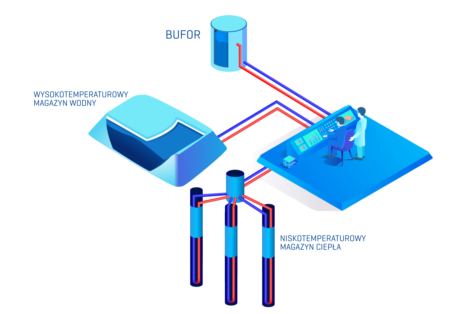
The first level of storage is a short-term storage in the form of a 100 m3 water tank (buffer) with a temperature range of operation from 60⁰C to 85⁰C. The purpose of the buffer is to maximize the self-consumption of locally produced electrical energy from PV panels and PVT collectors. Full self-consumption has been achieved by introducing additional electric heaters into the system, placed in the buffer. It should be emphasized that these heaters are powered solely by electric energy from PV and PVT installations and do not constitute a peak power source supplied from the power grid. The proposed solution allows not only for ensuring 100% share of RES in the production of hot water in the summer, but also for efficient local utilization of electrical energy produced by photovoltaic installations.

The second level of storage is a low-temperature ground storage characterized by high thermal capacity and storage efficiency. The ground storage consists of 300 ground heat exchangers with a length of 99.9 meters, and its temperature range of operation is 5⁰C to 15⁰C. The storage is charged during the summer with heat produced by heat pumps, for which the air heat exchanger is the lower heat source, and heat from hybrid PVT collectors. Heat pumps during the charging of the ground storage are powered solely by locally produced electric energy from PV and PVT installations. The cooperation of the PVT installation with the low-temperature ground storage allows for achieving better charging efficiency than cooperation with the high-temperature storage. The ground storage is mainly discharged in the fall and spring.
The last level of heat storage is a high-temperature water storage, consisting of a sealed, insulated earthen basin with a capacity of 15,000 m3, filled entirely with water. The storage temperature ranges from 7⁰C to 70⁰C. Thanks to the higher water temperatures in the high-temperature storage, heat pumps operate at high coefficients of performance COP. This is particularly important because the water heat storage is most often used in winter, in conditions of low outside temperatures, low production of electrical energy from PV and PVT installations, and higher required supply temperatures for the district heating network.
The layered arrangement of components in the Technology Demonstrator allows for a reduction in land use.
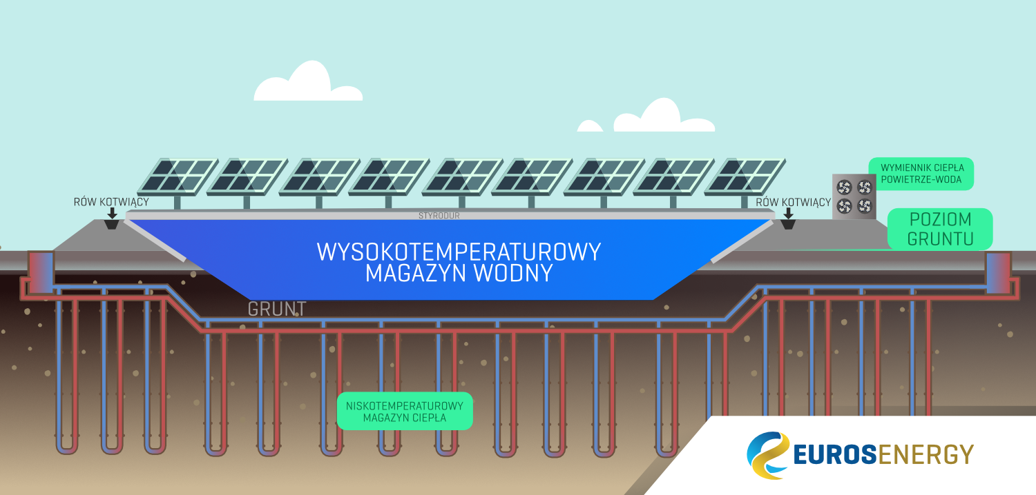
Due to the lower energy density of renewable sources compared to installations based on fossil fuels, in order to implement the Future Heating Technology, one must have a relatively large area – compared to the area occupied by installations based on the combustion of fossil fuels or biomass. In order to maximize the use of the available plot area and achieve the highest possible energy density for the Demonstrator Technology, individual installation elements are arranged in layers, as shown in Figure 6.
Throughout the plot area of the heating plant, boreholes will be distributed for the vertical ground heat exchangers. Then, on the same area, a water heat storage tank will be built, which will occupy approximately 40% of the ground surface with the ground exchangers. This solution not only increases the energy density of the system, but also provides additional insulation from the top of the ground storage tank. Furthermore, photovoltaic panels and PVT hybrid collectors will be installed on the walls and roof of the high-temperature water storage tank.
